Drop Down MenusCSS Drop Down MenuPure CSS Dropdown Menu
Showing posts with label Machines & Materials. Show all posts

Thursday, 14 April 2016

EQUIVALENT CIRCUIT, ROTOR SLIP and INDUCED TORQUE OF AN INDUCTION MOTOR

THE EQUIVALENT CIRCUIT OF AN INDUCTION MOTOR

An induction motor relies for its operation on the induction of voltages and currents in its rotor circuit from the stator circuit (transformer action). This induction is essentially a transformer operation, hence the equivalent circuit of an induction motor is similar to the equivalent circuit of a transformer.

The Transformer Model of an Induction Motor

A transformer per-phase equivalent circuit, representing the operation of an induction motor is shown below:
Transformer per-phase equivalent circuit of induction motor
As in any transformer, there is certain resistance and self-inductance in the primary (stator) windings, which must be represented in the equivalent circuit of the machine. They are - R1 - stator resistance and X1 – stator leakage reactance. 
Also, like any transformer with an iron core, the flux in the machine is related to the integral of the applied voltage E1. The curve of mmf vs flux (magnetization curve) for this machine is compared to a similar curve for a transformer, as shown below:
magnetization curve
Magnetization curve
The slope of the induction motor’s mmf-flux curve is much shallower than the curve of a good transformer. This is because there must be an air gap in an induction motor, which greatly increases the reluctance of the flux path and thus reduces the coupling between primary and secondary windings. The higher reluctance caused by the air gap means that a higher magnetizing current is required to obtain a given flux level. Therefore, the magnetizing reactance Xm in the equivalent circuit will have a much smaller value than it would in a transformer.
The primary internal stator voltage is E1 is coupled to the secondary ER by an ideal transformer with an effective turns ratio aeff. The turns ratio for a wound rotor is basically the ratio of the conductors per phase on the stator to the conductors per phase on the rotor. It is rather difficult to see aeff clearly in the cage rotor because there are no distinct windings on the cage rotor.
ER in the rotor produces current flow in the shorted rotor (or secondary) circuit of the machine.
The primary impedance and the magnetization current of the induction motor are very similar to the corresponding components in a transformer equivalent circuit.

The Rotor Circuit Model.

When the voltage is applied to the stator windings, a voltage is induced in the rotor windings. In general, the greater the relative motion between the rotor and the stator magnetic fields, the greater the resulting rotor voltage and rotor frequency. The largest relative motion occurs when the rotor is stationary, called the locked-rotor or blocked-rotor condition, so the largest voltage and rotor frequency are induced in the rotor at that condition. The smallest voltage and frequency occur when the rotor moves at the same speed as the stator magnetic field, resulting in no relative motion.
The magnitude and frequency of the voltage induced in the rotor at any speed between these extremes is directly proportional to the slip of the rotor. Therefore, if the magnitude of the induced rotor voltage at locked-rotor conditions is called,

ER0R = sER0
And the frequency of the induced voltage at any slip is:
fr = sfe

This voltage is induced in a rotor containing both resistance and reactance. The rotor resistance RR is a constant, independent of slip, while the rotor reactance is affected in a more complicated way by slip.
The reactance of an induction motor rotor depends on the inductance of the rotor and the frequency of the voltage and current in the rotor. With a rotor inductance of L
R, the rotor reactance is:
Rotor Reactance
Rotor Reactance
where XR0 is the blocked rotor reactance.
The rotor current flow is:
rotor current
rotor current
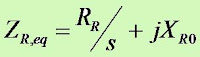
Therefore, the overall rotor impedance talking into account rotor slip would be:
rotor impedance
rotor impedance
In this equivalent circuit, the rotor voltage is a constant ER0 V and the rotor impedance ZReq contains all the effects of varying rotor slip. Based upon the equation above, at low slips, it can be seen that the rotor resistance is much much bigger in magnitude as compared to XR0. At high slips, XR0 will be larger as compared to the rotor resistance.

The Final Equivalent Circuit.

To produce the final per-phase equivalent circuit for an induction motor, it is necessary to refer the rotor part of the model over to the stator side. In an ordinary transformer, the voltages, currents and impedance on the secondary side can be referred to the primary by means of the turns ratio of the transformer.
Exactly the same sort of transformation can be done for the induction motor’s rotor circuit. If the effective turns ratio of an induction motor is a
eff , then the transformed rotor voltage becomes,
rotor voltage
rotor voltage
The rotor current:
rotor current
rotor current
And the rotor impedance:
rotor impedance
rotor impedance
If we make the following definitions:
R2 = a2eff RR
X2 = a2eff XR0
The final per-phase equivalent circuit is as shown below:
per-phase equivalent circuit of induction motor

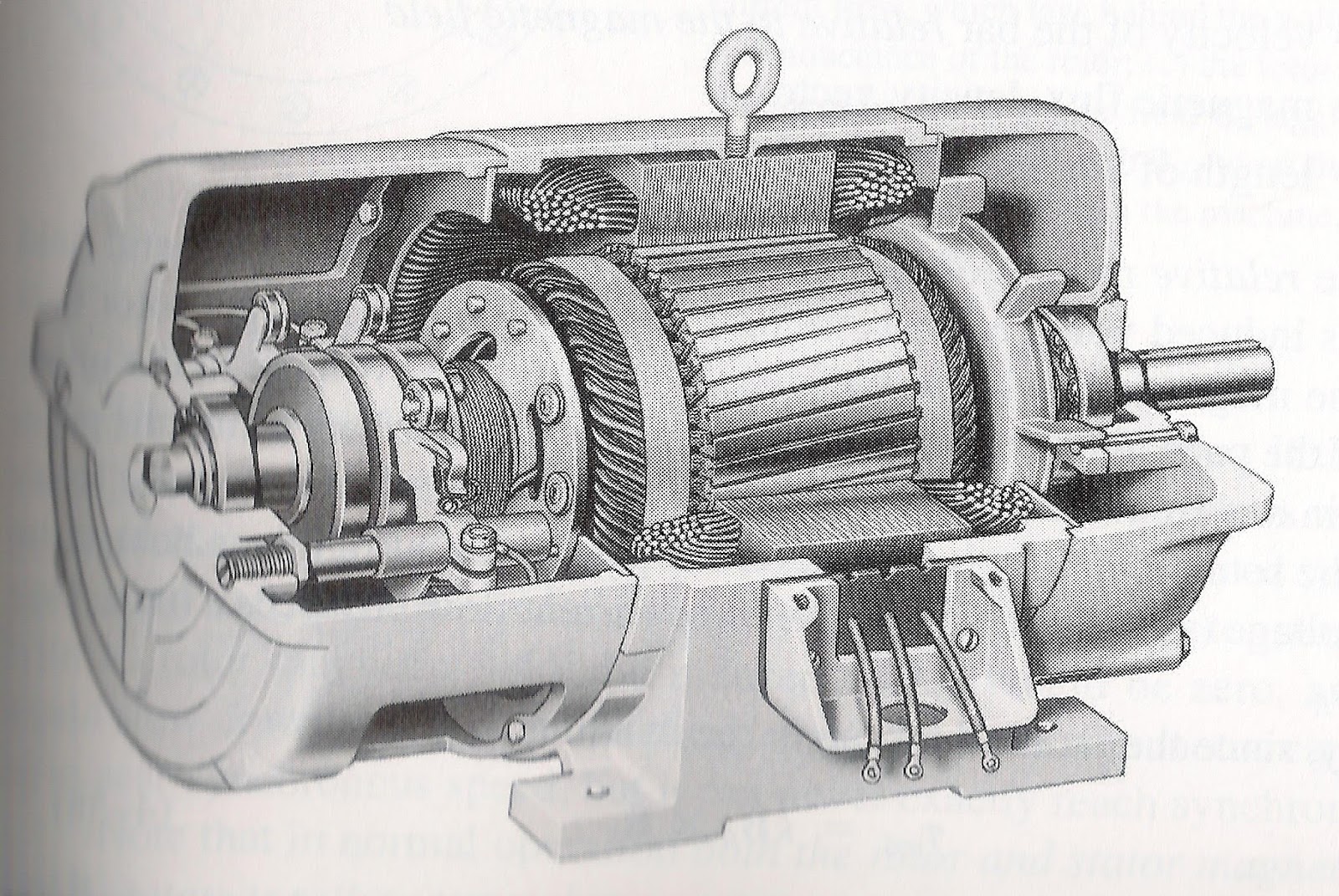
THE CONCEPT OF ROTOR SLIP IN AN INDUCTION MOTOR
sectional view of induction motor
The induced voltage at the rotor bar depends upon the relative speed between the stator magnetic field and the rotor. This can be easily termed as slip speed:
slip speed
slip speed
Where,
 nslip = slip speed of the machine
n
sync = speed of the magnetic field.
nm = mechanical shaft speed of the motor.
Apart from that we can describe this relative motion by using the concept of slip:

slip
slip
Slip may also be described in terms of angular velocity, w.
slip
slip
Using the ratio of slip, we may also determine the rotor speed:
rotor speed
rotor speed


THE DEVELOPMENT OF INDUCED TORQUE IN AN INDUCTION MOTOR.

INDUCTION MOTOR
INDUCTION MOTOR
When current flows in the stator, it will produce a magnetic field in stator as such that Bs (stator magnetic field) will rotate at a speed:
synchronous speed
synchronous speed
Where fe is the system frequency in hertz and P is the number of poles in the machine. This rotating magnetic field Bs passes over the rotor bars and induces a voltage in them. The voltage induced in the rotor is given by:
eind = (v x B) l
Hence there will be rotor current flow which would be lagging due to the fact that the rotor has an inductive element. And this rotor current will produce a magnetic field at the rotor, Br. Hence the interaction between both magnetic field would give torque:
INDUCED TORQUE
INDUCED TORQUE
The torque induced would generate acceleration to the rotor, hence the rotor will spin.
However, there is a finite upper limit to the motor’s speed.
DEVELOPMENT OF INDUCED TORQUE IN AN INDUCTION MOTOR
Conclusion : An induction motor can thus speed up to near synchronous speed but it can never reach synchronous speed.

Thursday, 3 September 2015

PERMANENT-MAGNET MATERIALS AND CHARACTERISTICS.

PERMANENT-MAGNET MATERIALS AND CHARACTERISTICS.

The sustained success of the permanent-magnet industry in developing improved magnet characteristics can be realised from the graph shown below;


The latest addition being neodymium-iron-boron which has been pioneered by Sumitomo as 'Neomax', General Motors as 'Magnequench', Crucible ('Crumax'), and IG Technologies ('NelGT'). At room temperature NdFeB has the highest energy product of all commercially available magnets. The high remanence and coercivity permit marked reductions in motor frame-size for the same output compared with motors using ferrite (ceramic) magnets. However, ceramic magnets are considerably cheaper.
Both ceramic and NdFeB magnets are sensitive to temperature and special care must be taken in design for working temperatures above 100
°C. For very high temperature applications Alnico or rare-earth cobalt magnets must be used, for example 2-17 cobalt-samarium which is useable up to 200°C or even 250°C.
NdFeB is produced either by a mill-and-sinter process (Neomax) or by a melt-spin casting process similar to that used for amorphous alloys (Magnequench). Powder from crushed ribbon is bonded or sintered to form
the MQI or MQII grades produced by Magnequench Division of GM. The MQI bonded magnets can be formed in a wide variety of shapes. They are not 100 per cent dense and coatings may be used to prevent corrosion. With MQII and other sintered materials a dichromate coating may be used, or electroplating.
For lowest cost, ferrite or ceramic magnets are the universal choice. This class of magnet materials has been steadily improved and is now available with remanence of 0.38 T and almost straight demagnetization characteristic throughout the second quadrant. The temperature characteristics of ferrite magnets can be tailored to the application requirements so that maximum performance is obtained at the normal operating temperature, which may be as high as 100°C.
A brief summary of magnet properties is given in the table below. More detail can be obtained from suppliers' data sheets, as the examples show. Specialist data and measurements are often made by permanent-magnet research and development bodies; for example, in the UK, the Magnet Centre at Sunderland Polytechnic, and in the USA, the University of Dayton, Ohio. Activity in magnet research is also well reported in IEEE and specialist conference proceedings.


B-H LOOP AND DEMAGNETIZATION CHARACTERISTICS: PERMANENT-MAGNET MATERIAL.


The starting-point for understanding magnet characteristics is the B-H loop or 'hysteresis loop'. In figure shown, the x-axis measures the magnetizing force or, 'field intensity' H in the material. The y-axis is the magnetic flux-density' B in the material. An magnetized sample has B = 0 and H = 0 and therefore starts out at the origin. If it is subjected to a magnetic field, as for example in a magnetizing fixture (an electromagnet with specially shaped pole pieces to focus flux into the magnet), then B and H in the magnet will follow the curve OA as the external ampere-turns are increased. If the external ampere-turns are switched off, the magnet relaxes along AB. Its operating point (H, B) will depend on the shape of the magnet and the permeance of the surrounding 'magnetic circuit'. If the magnet is surrounded by a highly permeable magnetic circuit, that is, if it is 'keepered', then its poles are effectively shorted together so that H—0 and the flux-density is then the value at point B, the remanence 
Br. The remanence is the maximum flux-density that can be retained by the magnet at a specified temperature after being magnetized to saturation.

External ampere-turns applied in the opposite direction cause the magnet's operating point to follow the curve from B through the second quadrant to C, and again if they are switched off at C the magnet relaxes along CD. It is now magnetized in the opposite direction and the maximum flux-density it can retain when 'keepered' is —
Br. To bring the flux-density to zero from the original positive remanence the external ampere-turns must provide within the magnet a negative magnetizing force —Hc, called the coercivity. Likewise, to return the flux-density to zero from the negative remanence point D, the field +Hc must be applied. The entire loop is usually symmetrical and can be measured using special instruments such as the Hysteresis graph made by Walker Scientific Instruments.

If negative external ampere-turns are applied, starting from point B, and switched off at R, the operating point of the magnet 'recoils' along RS. If the magnet is still 'keepered' the operating point ends up at point S. Now if the external ampere-turns are re-applied in the negative direction between S and R, the operating point returns along SR. The line RS is actually a very thin 'minor hysteresis loop' but for practical purposes it can be taken as a straight line whose slope is equal to the recoil permeability. This is usually quoted as a relative permeability, so that the actual slope of RS is 
µrecµ0 H/m. Operation along RS is stable provided that the operating point does not go beyond the boundary of the original hysteresis loop.

TEMPERATURE EFFECTS: REVERSIBLE LOSSES: PERMANENT-MAGNET MATERIALS

High-temperature effects: 

Exposure to sufficiently high temperatures for long enough periods produces metallurgical changes which may impair the ability of the permanent magnet
material to be magnetized and may even render it non-magnetic. There is also a temperature, called the Curie temperature, at which all magnetization is reduced to zero. After a magnet has been raised above the Curie temperature it can be re-magnetized to its prior condition provided that no metallurgical changes have taken place. The temperature at which significant metallurgical changes begin is lower than the Curie temperature in the case of the rare-earth/cobalt magnets, NdFeB, and Alnico; but in ceramic ferrite magnets it is the other way round. Therefore ceramic magnets can be safely demagnetized by heating them just above the Curie point for a short time. This is useful if it is required to demagnetize them for handling or finishing purposes. Table shows these temperatures for some of the important magnets used in motors

Reversible losses: 

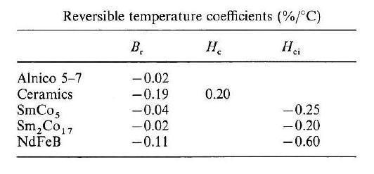
The B-H loop changes shape with temperature. Over a limited range the changes are reversible and approximately linear, so that temperature coefficients for the remanence and coercivity can be used. Sometimes a coefficient is also quoted for the flux density at the maximum-energy point. The table shown, gives some typical data. Ceramic magnets have a positive coefficient of Hc , whereas the high-energy magnets lose coercivity as temperature increases.

In ceramic magnets the knee in the demagnetization curve moves down towards the third quadrant, and the permeance coefficient at the knee decreases. Thus ceramic magnets become better able to resist demagnetization as the temperature increases up to about 120°C. The greatest risk of demagnetization is at low temperatures when the remanent flux density is high and the coercivity is low; in a motor, this results in the highest short-circuit current when the magnet is least able to resist the demagnetizing ampere-turns. In high-energy magnets the knee moves the other way, often starting in the third quadrant at room temperature and making its way well into the second quadrant at 150°C. Grades with a high resistance to temperature are more expensive, yet these are often the ones that should be used in motors, particularly if high temperatures are possible (as they usually are under fault conditions).
All the magnets lose remanence as temperature increases. For a working temperature of 50°C above an ambient of 20°C, for instance, a ceramic magnet will have lost about 10 per cent. This is spontaneously recovered as the temperature falls back to ambient.

TEMPERATURE EFFECTS: IRREVERSIBLE LOSSES: PERMANENT-MAGNET MATERIALS


Domain relaxation: 

Immediately after magnetization there is a very slow relaxation, starting with the least stable domains returning to a state of lower potential energy. The relaxation rate depends on the operating point and is worse below (BH)max , i.e. at low permeance coefficients.
In modern high-coercivity magnets at normal temperatures this process is usually negligible, particularly if the magnets have been stabilized (by temperature cycling and/or a.c. flux reduction) immediately after magnetization. Elevated temperatures during subsequent operation may, however, cause an increased relaxation rate. This can be prevented by temperature-cycling in the final assembly over a temperature range slightly wider than the worst-case operating range. Subsequent relaxation is reduced to negligible levels by this means. The 'natural' stability of different magnet materials at 24°C, is shown below,


Operating point effect: 

Temperature alters the B-H loop. If this causes the operating point to 'fall off' the lower end of a recoil line, there will be an irreversible flux loss. This is illustrated in image below.
Operation is initially at point a on the load line 0a, which is assumed to remain fixed. The remanent flux-density corresponding to point a is at point A. When the temperature is raised from T1 to T2 the operating point moves from a to b, and the corresponding remanent flux-density moves from A to B'.
Note that because the knee of the curve has risen above point b, the effective remanent flux-density is at B and is less than that at B', which is what it would have been if the magnet had been working at a high permeance coefficient.


If the temperature is now reduced to 
T1 the operating point can recover only to a', which lies on the recoil line through A'. There has been a reversible recovery of remanence from B' to A', but not to A. The magnet has thus suffered an irreversible loss that can be recovered only by re-magnetization at the lower temperature. If the whole cycle of changes is repeated it stabilizes with the remanence at A' at the lower temperature T1.
Manufacturers' data for irreversible loss should be interpreted carefully to distinguish between the long-term stability and the effects just described. Since the irreversible loss is dependent on the conditions of the application, in particular the permeance coefficient, irreversible loss is usually quoted at a fixed permeance coefficient. If the magnet is used at a higher permeance coefficient, the irreversible loss over the same temperature range will be lower.

Monday, 17 August 2015

DC MACHINE CONFIGURATION.

DC MACHINE CONFIGURATION.
A simple two-pole stator of a DC machine is shown in figure below. The field winding consists of an N turn concentrated winding of which each half is wrapped around a pole. The two parts of the winding are connected in series and attached to a DC power supply. The frame is in this case also
the yoke-part of the magnetic flux path. The use of a field winding gives us the ability to control the magnetic flux in the circuit in terms of amplitude and polarity. Permanent magnets are often used to replace the field winding which leads to a more compact and efficient machine. However, we loose in practical terms one degree of freedom, as we are now unable to control (in electrical terms) the flux magnitude during operation. We also loose the potential of operating the machine on an AC source, therefore universal machines (AC/DC) always have a field winding and no permanent magnets.
A very simple example of a DC rotor is given in figure, which shows the same single turn winding introduced for the synchronous machine. In this case, the slip ring/brush combination is replaced by a so-called commutator. This commutator consists, for this simple rotor, of two brushes and two commutator segments. Segment 1 and 2 are connected to coil side A and B respectively.
The brushes are connected to a direct current (DC) power supply. The purpose of the commutator is to reverse the current polarity in the rotor winding every half revolution in this case. For example, in the case shown, coil side A is connected via segment 1 and a brush to terminal 1. Likewise side B is connected via segment 2 and a brush to terminal 2. When we rotate the rotor by 180 degrees, side A will be electrically connected to terminal 2 and side B to terminal 1. This means that a current reversal in the winding will take place twice during one period. In reality the number of segments is greater than 2 and this has a marked effect on the torque ripple.

Friday, 7 August 2015

The Equivalent Circuit of a Synchronous Generator

THE EQUIVALENT CIRCUIT OF A SYNCHRONOUS GENERATOR

The internal generated voltage produced in one phase of a synchronous generator can be called as EA.  If the machine is not connected to a load (no armature current flowing), the terminal voltage will be equivalent to the voltage induced at the stator coils. This is due to the fact that there are no current flow in the stator coils hence no losses. When there is a load connected to the generator, there will be differences between EA and Vf. These differences are due to:

a)      Distortion of the air gap magnetic field by the current flowing in the stator called armature reaction.

b)      Self inductance of the armature coil

c)      Resistance of the armature coils

d)      The effect of salient pole rotor shapes.


We will explore factors a, b, and c and derive a machine model from them.  The effect of salient pole rotor shape will be ignored, and all machines in this chapter are assumed to have non salient or cylindrical rotors. 

Armature Reaction

When the rotor is spun, a voltage EA is induced in the stator windings.  If a load is attached to the terminals of the generator, a current flows.  But a 3-phase stator current flow will produce a magnetic field of its own.  This stator magnetic field will distorts the original rotor magnetic field, changing the resulting phase voltage.  This effect is called armature reaction because the armature (stator) current affects the magnetic field, which produced it in the first place. 

Refer to the diagrams below, showing a two-pole rotor spinning inside a 3-phase stator.

  •  A rotating magnetic field produces the internal generated voltage EA.
  • The resulting voltage produces a lagging current flow when connected to a lagging load.
  •  The stator current produces its own magnetic field BS which produces its own Estat in the stator windings.
  • The field BS adds to BR distorting it into Bnet.  The voltage Estat adds to EA, producing Vf at the output of the phase.

    (a)    There is no load connected to the stator. The rotor magnetic field BR produces an internal generated voltage EA whose peak coincides with direction of BR.  With no load, there is no armature current and EA will be equal to the phase voltage Vf.   
    (b)    When a lagging load is connected, the peak current will occur at an angle behind the peak voltage.
    (c)    The current flowing in the stator windings produces a magnetic field of its own.  This stator magnetic field BS and its direction are given by the right-hand rule.  The stator field produces a voltage of its own called Estat. 
    (d)    With 2 voltages and 2 magnetic fields present in the stator windings, the total voltage and the net magnetic field are:

How can the effects of armature reaction on the phase voltage be modeled?


-          The voltage Estat lies at an angle of 90° behind the plane of IA. 

-          The voltage Estat is directly proportional to the current IA. 


If X is a constant of proportionality, then the armature reaction voltage can be expressed as:

Therefore:


Thus, the armature reaction voltage can be modeled as an inductor in series with the internal generated voltage.

Self-inductance and Resistance of the Armature Coils

If the stator self-inductance is called LA (reactance is XA) while the stator resistance is called RA, then the total difference between EA and Vf is:


Where XS = X + XA,
The full equivalent circuit is shown below:


A dc power source is supplying the rotor field circuit, which is modeled by the coil’s inductance and resistance in series.  In series with RF is an adjustable resistor Radj which controls the flow of the field current.  The rest of the equivalent circuit consists of the models for each phase.  Each phase has an internal generated voltage with a series inductance XS (consisting of the sum of the armature reactance and the coil’s self-inductance) and a series resistance RA. 

If the 3 phases are connected in Y or ∆, the terminal voltage may be found as follows:


Ideally, the terminal voltage for all 3 phases should be identical since we assume that the load connected is balanced. If it is not balanced, a more in-depth technique is required.

The per-phase equivalent circuit: